- Â
B Reference
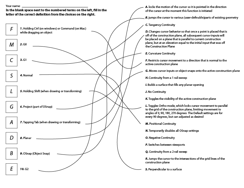
B Surface Toolpaths Tutorial
The section on the Bank CNC training website listed below has a thorough tutorial you should follow along to for creating surface toolpaths in MasterCAM.
B Updating Your MasterCAM file with New Geometry From Rhino
Some of you have asked: Is there a way to update the geometry in MasterCAM when I make changes in Rhino, like you can do with the Keyshot plugin?
There is not a plugin that links the two applications like Keyshot has with Rhino, but there is a fairly simple way to accomplish something similar:
- update the geometry you want to change in Rhino.
- In Rhino, select only the geometry you want to update and run the command “export” to save only this geometry.
- In MasterCAM, select the geometry that you would like to update. Delete this geometry by clicking the delete key (on mac you may need to press the “FN” key + delete. If this geometry is used by a toolpath operation you will get a warning, click OK. This is just warning you that a toolpath is using the geometry you are about to delete.
- Merge the updated geometry you exported in step #2. You may want to use the technique covered in a previous post to make sure the layer structure is preserved, but sometimes merging in new geometry messes up the layers.
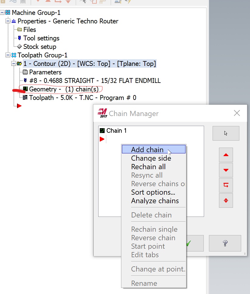
- Go into the operations that should use the updated geometry and add the updated geometry to this to the operation. To do this, expand the toolpath operation, click on the entry for “geometry”, then right-click in the “chain manager” window and pick “add chain”.
- When finished adding chains, click the green check to exit the chain manager, then regenerate the operations to calculate these changes.
You can use the same technique to add additional geometry or to otherwise change the geometry that is associated with a specific toolpath operation.
B Problem: Merging Geometry from Rhino in MasterCAM Doesn’t Include Layer Structure?
Some of you may be experiencing a problem where your layers are not preserved upon merging from Rhino into MasterCAM. Here is the workaround to solve this problem:
- Make sure you “export” from Rhino only the geometry you need for your work in MasterCAM
- go to File>Merge in MasterCAM, browse to the file you want to merge, select it, and click “Open”
- One the left side of the MasterCAM application you will see the Merge options. Click on the check box for “Use current attributes” to turn this option on, then click on it again to turn it off
- if you look at the “Levels” panel, you can verify that the layer structure is preserved – you should see the named layers from Rhino with the appropriate number of objects per layer.
- Click on the green check symbol to complete the merging of geometry

B Setting Defaults in MasterCAM
This video shows you how to set defaults in MasterCAM, so you don’t need to enter them each time you work with it.
B MasterCAM – Recommended Settings for Contour, Pocket, Drill
See the PDF below for recommended settings for MasterCAM:
B Sample Stool Rhino and MasterCAM files
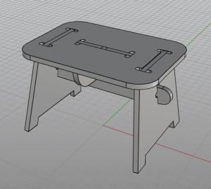
Here is a link to the mastercam and rhino reference files for the step stool we looked over in class Monday. There’s also the rhino 3d file of the stool. You can use the layer conventions shown in the rhino file to help simplify your operation selection in MasterCAM https://drive.google.com/drive/folders/1LHZFsByQpyNWEn0OLK5sicsPlSjzzFAx?usp=sharing
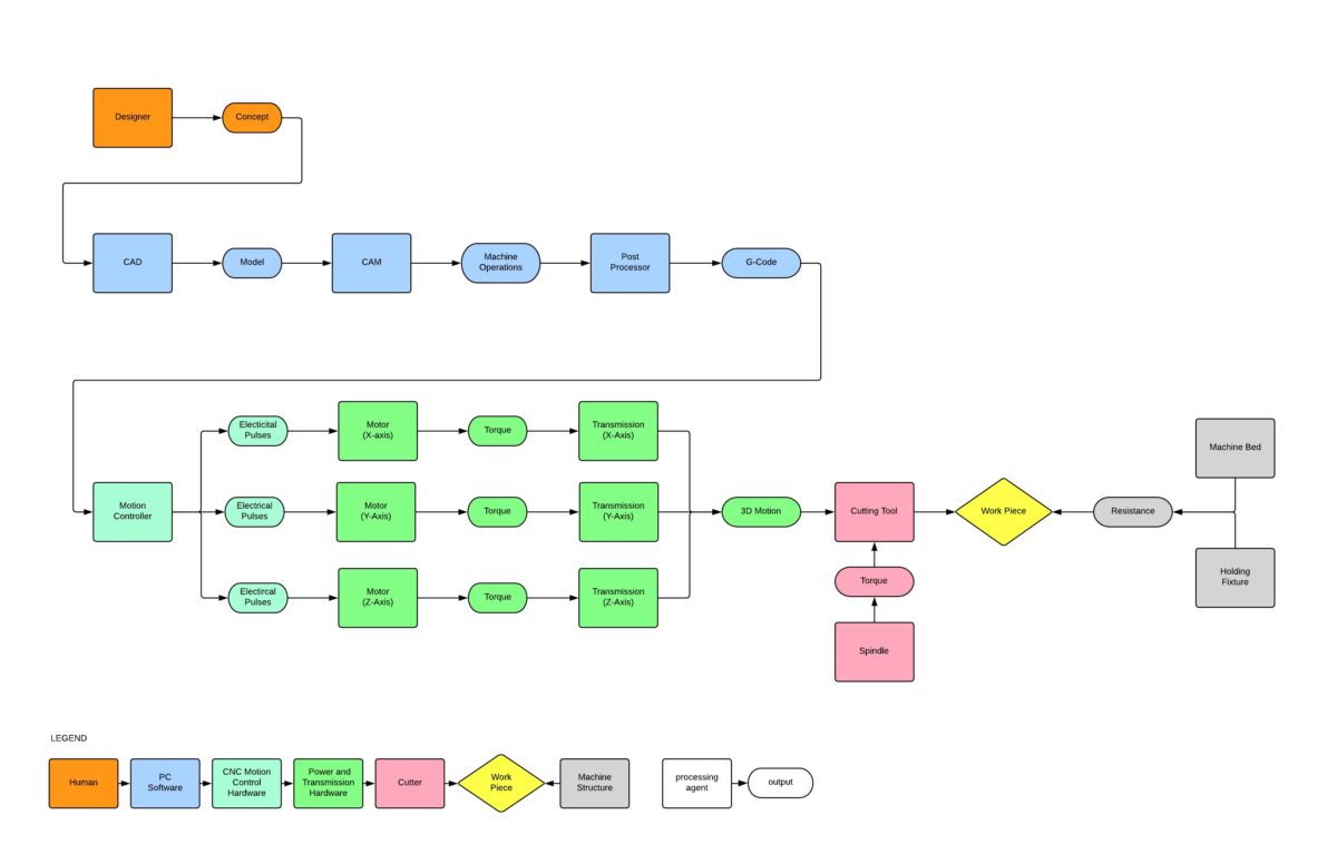
B CNC Machining Diagram
This diagram illustrates the flow from concept to part in a CNC machining process.
B Texture Mapping and Labels in Keyshot
This video provides a nice overview of texture mapping in Keyshot
And related, is an introduction to labels
B Unroll Surface Video Demonstration
This video provides an in depth review of the “Unroll” command
You can download the model used in this video here.
B Video Review of Make2D
If you’re looking for a review of the Make2D command that was covered in class, here’s a video that provides a quick refresher. FYI – this video isn’t mine – it’s from Polyplane.com
B Mustard Bottle Tutorial
Download this PDF file which covers the steps to build the mustard bottle shown below.
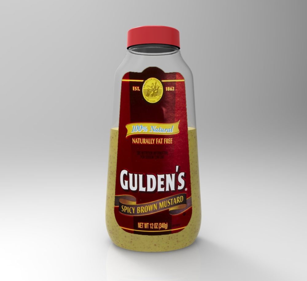
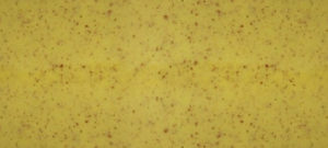
Create a rendering of your completed bottle. You can use the the mustard image below as a texture map for the mustard, and the image of the label as a “label” in Keyshot.

B Surfacing Tools Demonstration
You can download this file to follow along during the demonstration of surfacing tools.
B Saving as .STL for 3D Printing
In order to 3D print a model of one of your glasses, you will need to export it as an .STL file.
To do so you can follow these steps from Rhino:
- make sure the object is a solid. You can run the command “What” and if this tells you that the object is “closed” it is a sold. If it does not say it is cloed, you can run the command ShowEdges – this will allow you to display “naked” edges (edges that are not connected to another edge). If your model has naked edges, these are the edges that are open. If the opening is very small, the 3D printing software should be able to process your file successfully. The lab also has software that can “heal” small openings.
- Select the object, and then run the command “Export“. This will allow you to save only what you have selected.
- For the file format, choose .STL. Name your file and include your last name for easy reference in the 3D printing lab. Click export.
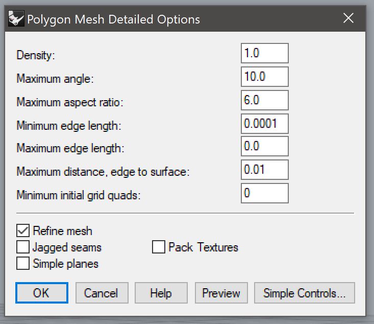
- a simple control dialogue will appear. On Windows, look for the option for “Detailed Controls”, on Mac you will see a little downward facing triangle. Use the settings shown below to ensure your model translates to a high resolution print
- Density: 1
- Maximum Angle: 10
- Maximum Aspect Ratio: 6
- Minimum Edge Length: .0001
- Maximum Edge Length: 0
- Maximum Distance, Edge to Surface: .01
- Maximum Initial Grid Quads: 0
- Refine Mesh: On
- Jagged Seams: Off
- Simple Planes: Off
- Pack Textures: Off
- You can click “Preview” to see how your model will be translated to planar polygons. Unless something looks really off, you can proceed by clicking “OK”
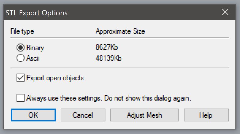
- In the next dialogue box, set the file type to binary and check the box for “Export Open Objects”, then click “OK”
Here are some screen shots showing the settings described above:
This file is now ready for 3D Printing. The monitors in the 3D printing lab in Bank building can you help you with the next steps.
B “History” functionality in Rhino
We didn’t look at this in class, but the “History” functionality in Rhino could be very useful as you are work on building the three bentwood chairs. This functionality will link input and output geometry. In other words, it can connect a curve (input geometry) with a pipe (output geometry) so that if the input curve is manipulated, the resulting output surface will follow this change.
More information here:
http://docs.mcneel.com/rhino/5/help/en-us/commands/history.htm
-
Classroom
-
